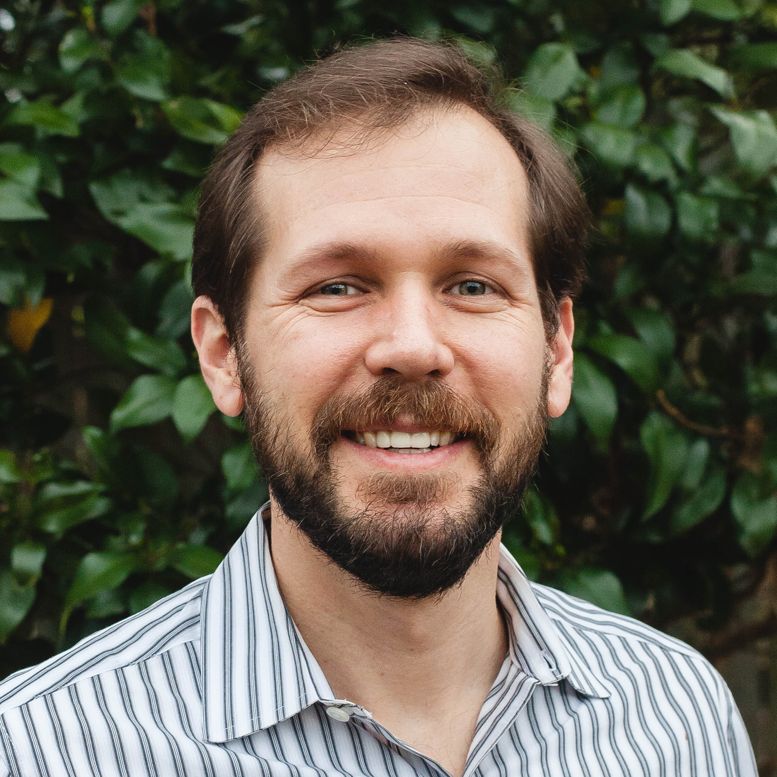
Director of Projects
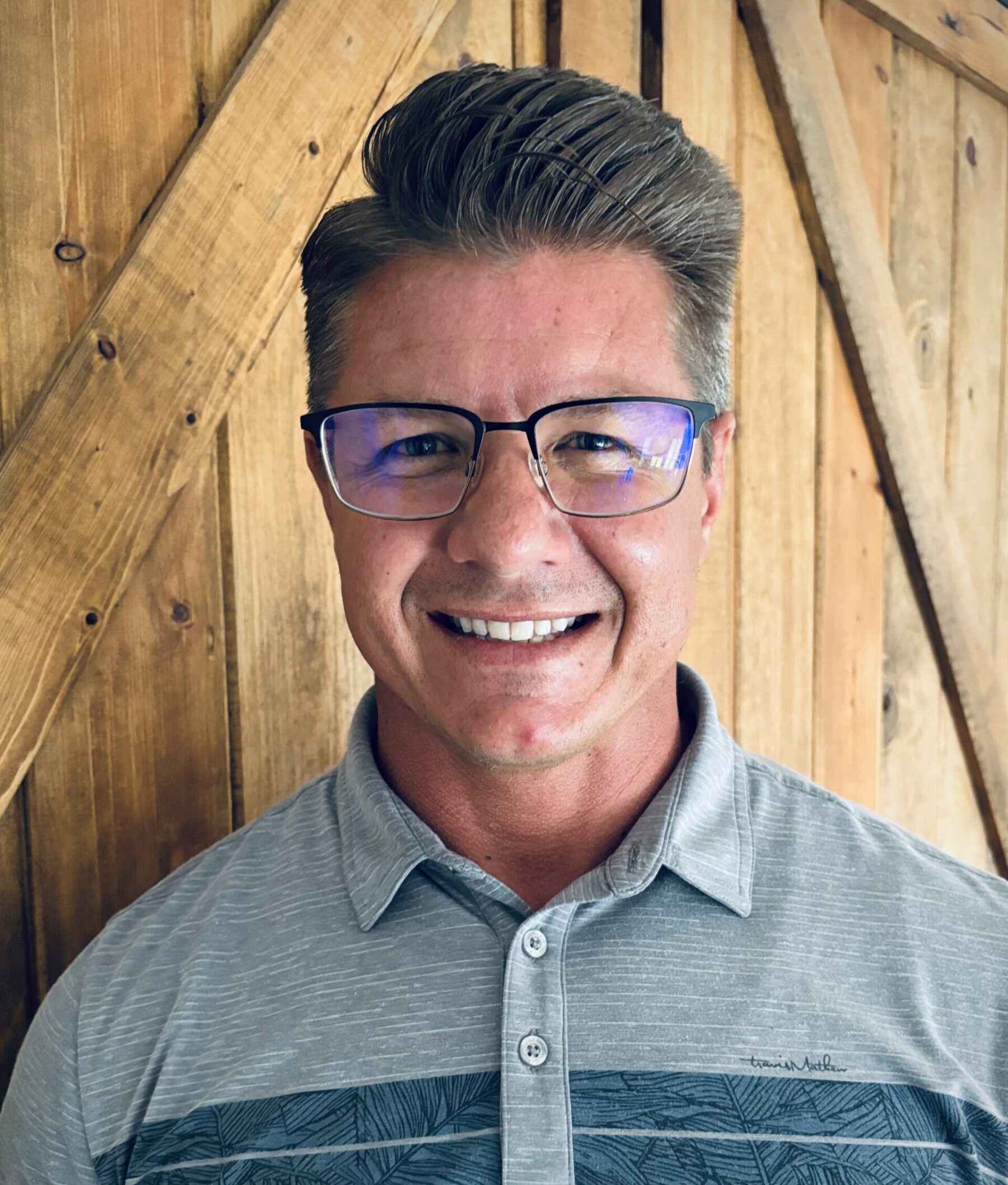
 Curtis Anderson is a seasoned Projects Director at Halker, specializing in managing projects for electric utilities and renewable energy companies, including high voltage power, solar, wind, and battery energy storage systems (BESS). Prior to his current role, Curtis held various leadership positions with 12 years in the industry. As Technology Innovation Manager, he was instrumental in establishing and leading a Product and Innovation team within the Power and Renewables Industry, driving technology enablement initiatives, and fostering a culture of innovation. His work included guiding the development of new products, implementing AI-driven solutions, and supporting the launch of industry-first SaaS offerings. Curtis also played a key role in business-to-business collaborations, strategic planning, and served as a member of an Artificial Intelligence Governance Board, focusing on enhancing operational efficiency through technology and R&D efforts.
Earlier in his career in the Power and Renewables Industry, Curtis served as Program Manager and Project Manager, where he led project management teams handling portfolios valued between $600 million and $2.5 billion. His responsibilities included managing scope, schedules, and budgets for major capital projects in the utility sector, fostering client relationships, and contributing to company-wide initiatives such as DEI programs, billing and forecasting tools, and M&A integration planning. Before entering the renewables sector, Curtis worked as an Independent Consultant and Mine Development Manager in the mining industry, where he managed mining operations, spearheaded acquisition strategies, and ensured regulatory compliance.
With a strong background in both traditional and renewable energy sectors, Curtis brings a wealth of expertise in project execution, innovation, and strategic leadership.
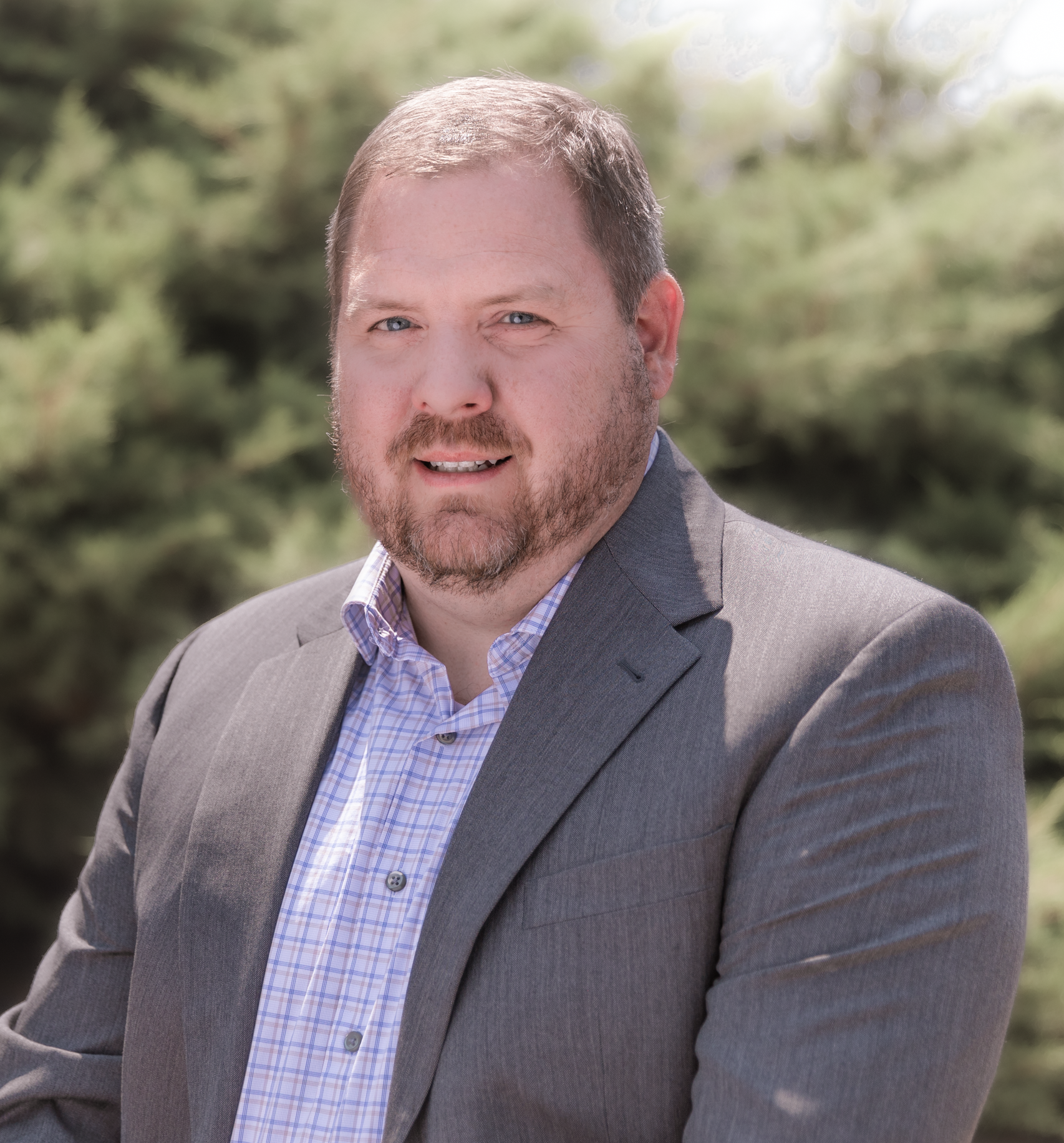
 Shannon McKibben is the director of Environmental Engineering at Halker, executing environmental, health, and safety projects for clients in construction, oil & gas, transportation, and power delivery. Under Shannon’s leadership, Halker’s Environmental Engineering group is actively diversifying from its historical role serving primarily road and highway construction clients into a support group for all of Halker’s projects, focusing on energy delivery and development.
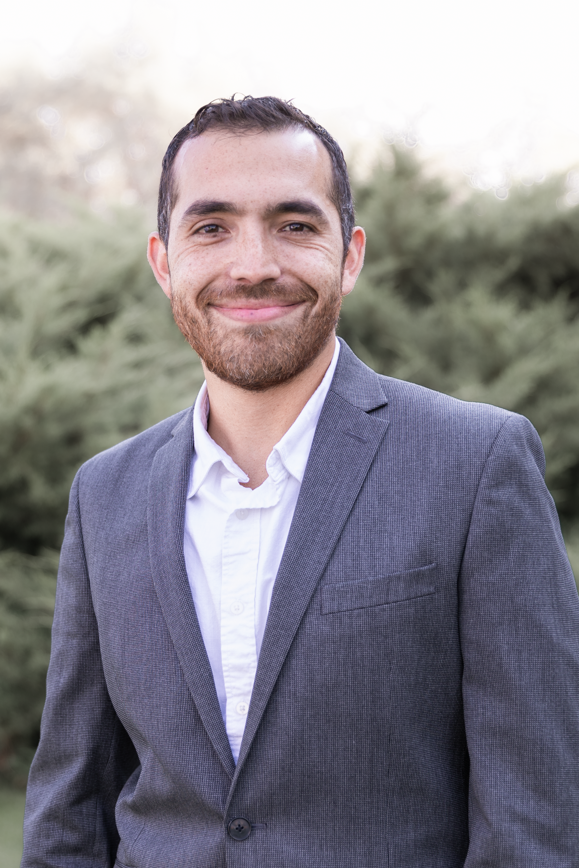
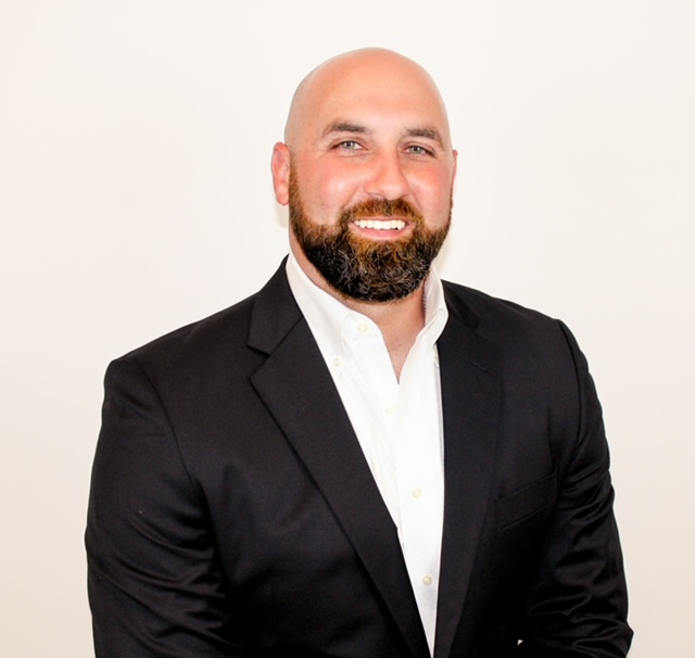 Dominic brings over 15 years of leadership in privately held and PE‑backed firms. Dominic’s experience in the energy industry expands across several sectors, including refining, midstream & pipeline and delivering fully modular facility solutions in the upstream production arena. Dominic has been involved in the sales and project management of more than 30 fully modular facilities in the Permian basin. He has built scalable go‑to‑market strategies that have helped drive impressive revenue growth: from $10M to $25M at Welker, and launching Petrosmith’s Modflex line to $40M in three years, while more than doubling revenue with its largest client.
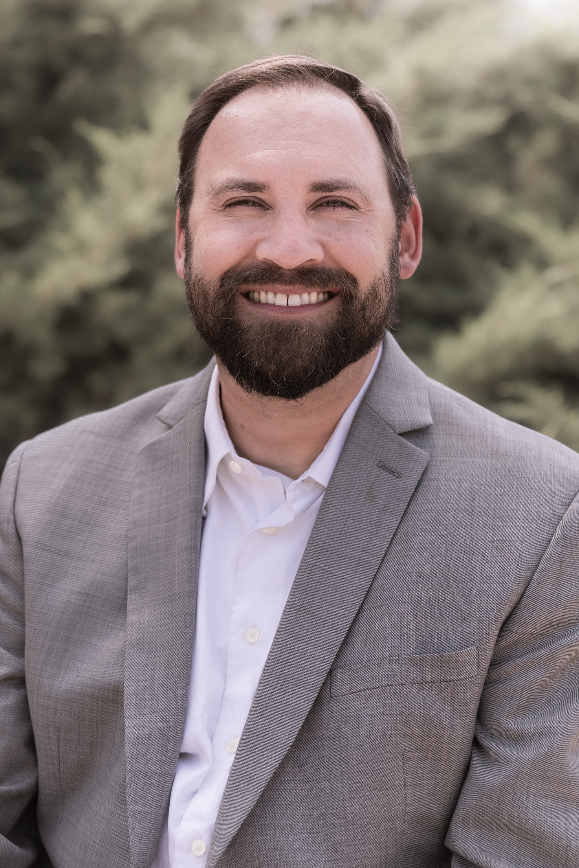

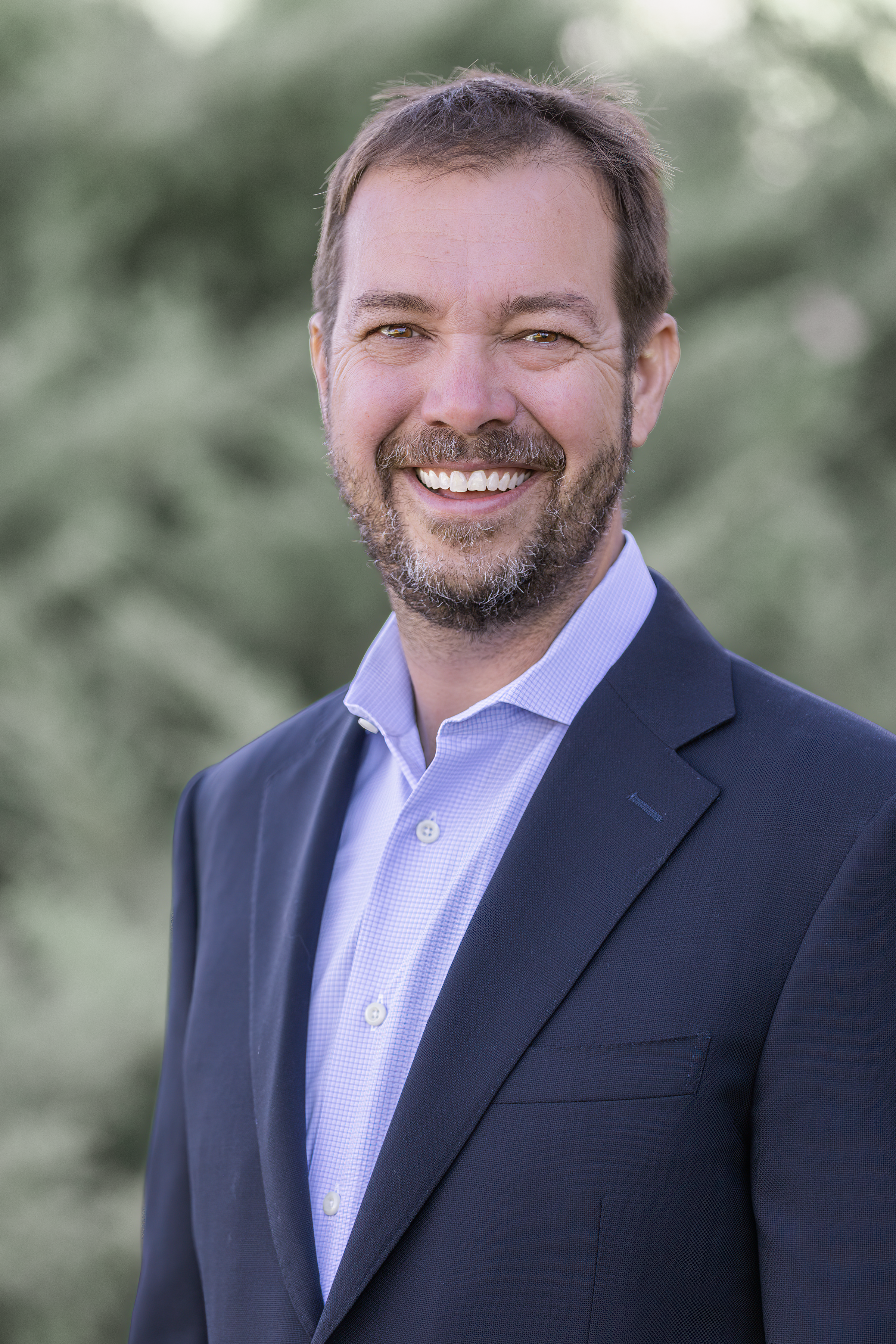
 Philip Barr joined Halker in April 2023. With nearly 20 years of structural engineering experience, he has contributed to projects across the oil and gas, pharmaceutical, chemical, mining and metals, and manufacturing industries. Philip has successfully led structural design teams in executing projects totaling over one billion dollars in value. He has also worked internationally as a field engineer and client representative, gaining valuable experience in constructability, modular design, and retrofit construction. As Halker’s Director of Structural Engineering, Philip draws on his extensive background and technical expertise to deliver innovative and cost-effective structural solutions for clients across a wide range of industries.
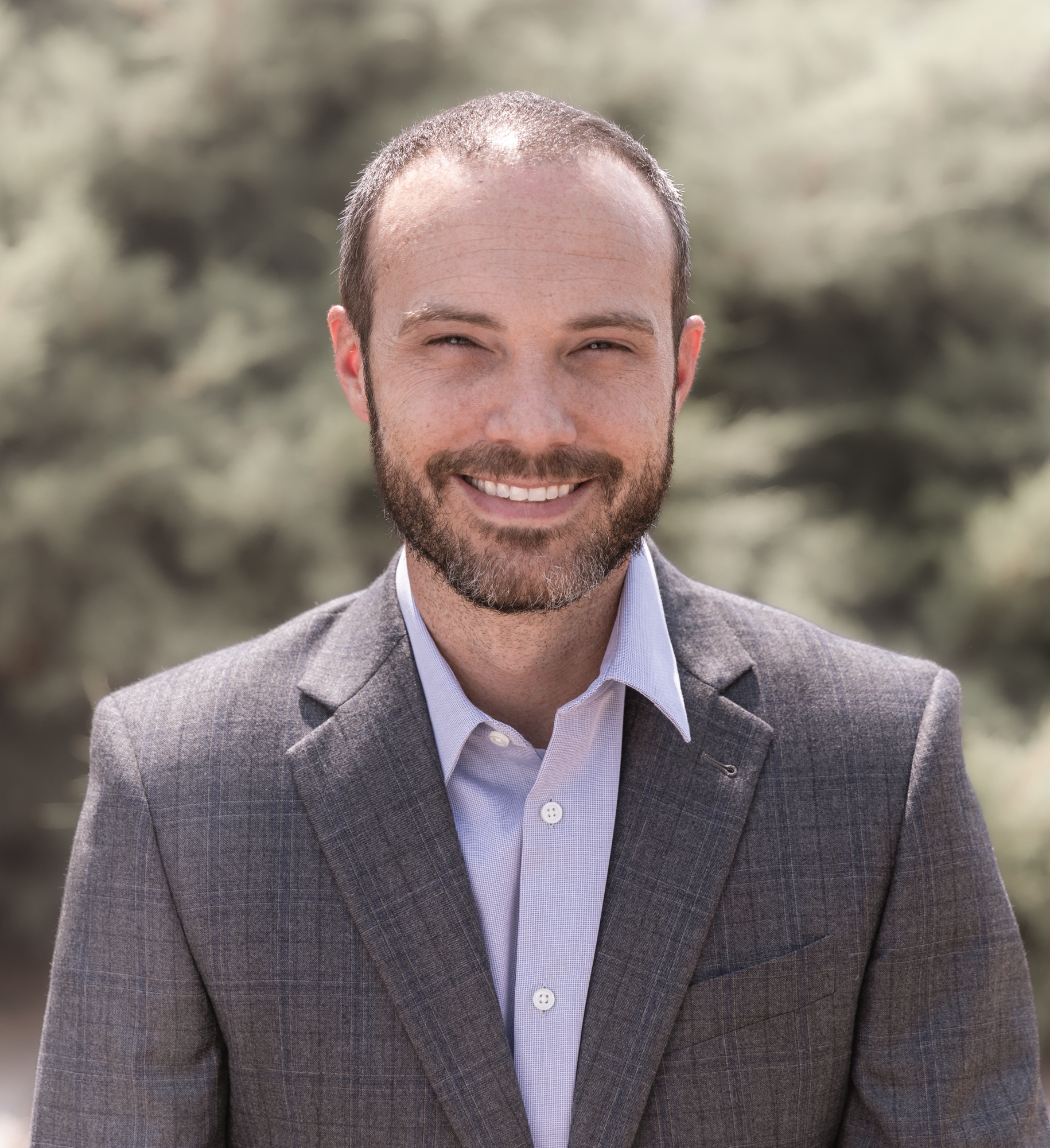
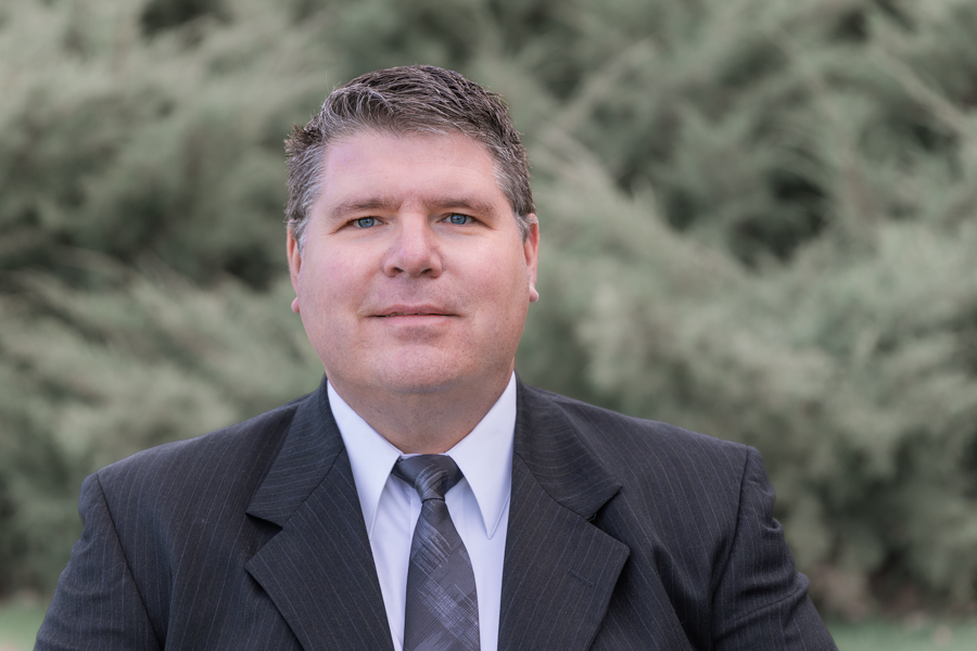
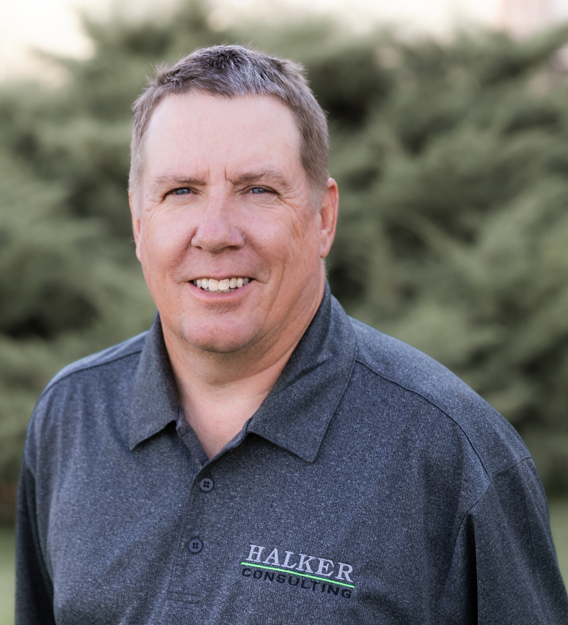
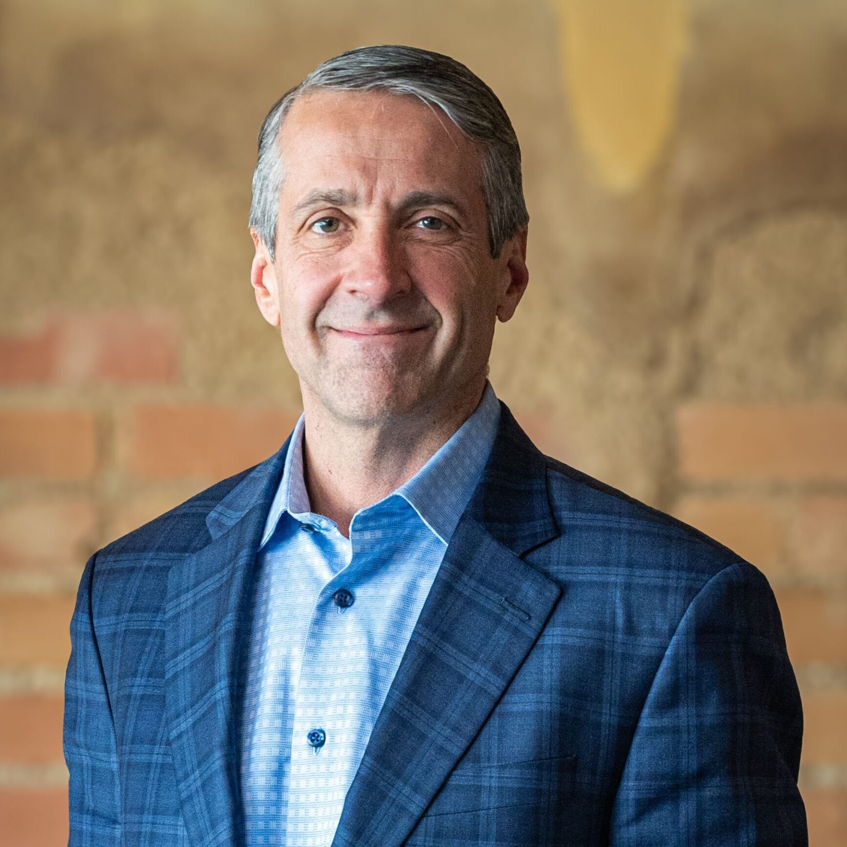
 Cory Shattuck is the Vice President of Power Services at Halker, based in Centennial, Colorado. With a career spanning roles such as Director of Power Delivery, Utility-scale Solar Technical Manager, Substation Technical Manager, and various engineering positions, Cory brings a wealth of experience to the energy sector. Cory’s expertise includes substation design, medium-voltage underground collection systems, electrical studies, and relay settings. In his current role, he leads the Power Services division, overseeing project execution, technical excellence, and strategic growth. His leadership is grounded in a commitment to quality, safety, and innovation in power delivery solutions. He has served as a Quality Manager for a key client and contributed to both Quality and Safety Committees. Cory holds a Bachelor of Science in Electrical Engineering from the South Dakota School of Mines and a Master of Business Administration from Colorado State University. He is also a licensed Professional Engineer.